
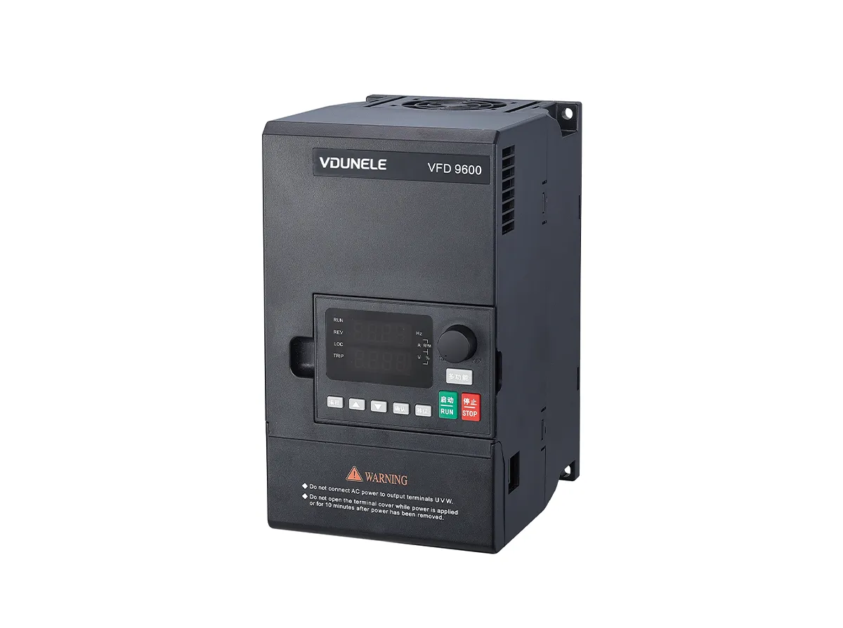
VFD9600M Economical Universal Variable Frequency Drive

VFD9600M Economical Universal Variable Frequency Drive
The VFD9600M series inverter is a classic entry-level vector control product developed by VDUNELE Technology to meet general market demands. Inheriting the stable and reliable heritage of its predecessors, this series offers a lightweight, efficient, and user-friendly motor drive solution with streamlined functionality and highly competitive cost-effectiveness. It is particularly suited for applications where moderate requirements for control precision and budget coexist. Designed around the core principles of “practicality, reliability, and economy,” it delivers adequate control performance and expandability while fulfilling basic speed regulation and energy-saving needs. The VFD9600M is an ideal entry-level choice for users transitioning from traditional fixed-speed drives to variable frequency control, especially well-suited for cost-sensitive, general-purpose industrial scenarios that do not require complex process integration.
1. Stable and Reliable Core Performance
Supports both V/F control and current vector control modes, balancing simplicity for basic applications and economic efficiency.
Offers multiple operation curves (light, medium, and heavy load) to match different load types.
Wide input voltage design (380V–480VAC, ±15%) to accommodate grid fluctuations.
Comprehensive protection functions, including overcurrent, overvoltage, undervoltage, and overtemperature safeguards.
2. Simple and Rapid Commissioning and Operation
Equipped with a detachable display and operation panel, featuring a clear parameter structure for easy setup.
Supports motor parameter self-learning (static identification) to enhance control accuracy.
Built-in multiple sets of programmable terminals, enabling basic logic control and multi-step speed operation.
Includes PID control functionality for direct use in closed-loop applications such as constant pressure or temperature control.
3. Lightweight Structure and Cost-Effective Design
Compact chassis design to save installation space.
Power range covers 0.4kW to 22kW, suitable for various motor power levels.
Supports the standard Modbus-RTU communication protocol for easy networking with PLCs, HMIs, and other devices.
Comes standard with a braking unit to meet general braking requirements.
4. Broad Application Adaptability
Suitable for energy-saving retrofits in fans, pumps, air compressors, and similar applications.
Applicable to simple transmission equipment such as conveyor belts, mixers, and packaging machines.
Supports one-drive-to-multiple-motor control (with parameter matching) for simple multi-motor systems.
Typical Application Areas
General mechanical equipment drives
Energy-saving control for fan and pump loads
Drives for small automated production lines
Light industrial equipment in food, textile, packaging, and related sectors
| VFD9600M series technical performance | |||
| Project | Indicators and specifications | ||
| Input | Rated voltage frequency | Three phase (T4 series) 380V; 50/60HZ three-phase (T2 series) 220V; 50/60HZ | |
| Voltage allowable variation range | Three phase (T4 series) 320V~460V Three phase (T2 series) 190V~250V | ||
| Output | Voltage | T4 series; 0-380VT2 series; 0~220V | |
| Frequency | V/F control, advanced V/F control, simple vector control: 0.0~999.9HZ, advanced vector control, torque control: 0.5~300.0HZ | ||
| Overload capacity | 110% long-term, 150% 1 minute, 180% 5 seconds | ||
| Control mode | V/F control, simple vector control, advanced vector control, torque control | ||
| Control characteristics | Frequency setting resolution | Analog input | 0.1% of maximum output frequency |
| Digital settings | 0.1Hz | ||
| Frequency accuracy | Analog input | Within 0.2% of the maximum output frequency | |
| Digital input | Set output frequency within 0.01% | ||
| V/F control | V/F curve (voltage frequency characteristics) | There are three methods: the first is the linear torque characteristic curve; The second type is the squared torque characteristic curve; The third method is for users to set the V/F curve. | |
| Torque increase | Manual setting: 0.0~30.0% of rated output Automatic increase: Automatically determine the increase torque based on output current and motor parameters | ||
| Automatic current and voltage limiting | During acceleration, deceleration, or stable operation, the motor stator current and voltage are automatically detected and suppressed within the allowable range using a unique algorithm, minimizing the possibility of system failure tripping. | ||
| Senseless vector control | Voltage frequency characteristics | Automatically adjust the output voltage frequency ratio based on motor parameters and unique algorithms. | |
| Torque characteristics | Starting torque: 100% rated torque at 5.0Hz (V/F control); 150% rated torque at 1.0Hz (vector control). Current and voltage suppression with full current closed-loop control, completely avoiding current surge, and equipped with comprehensive overcurrent and overvoltage suppression function. | ||
| Under voltage suppression during operation | Especially for users with low grid voltage and frequent fluctuations in grid voltage, even within the allowable voltage range, the system can maintain the longest possible operating time based on unique algorithms and residual energy allocation strategies | ||
| Typical functions | Multi speed operation | 7-stage programmable multi speed control with multiple operating modes to choose from. | |
| PID control RS485 communication | Built in PID controller (with preset frequency). Standard configuration RS485 communication function, multiple communication protocols optional, with linkage synchronization control function | ||
| Frequency setting | Analog input | DC voltage 0-10V, DC current 0-20mA (upper and lower limits optional). | |
| Digital input | Operation panel settings, RS485 interface settings, UP/DOWN terminal control, and can also be combined with various input settings. | ||
| Output signal | Relay output | 1 relay output (TA. TC) with up to 17 meaning options. | |
| Analog onput | 1 channel of analog signal output, with a flexible output range between 0~20mA or 0~10V, which can achieve frequency setting. Simulate the output of physical quantities such as output rate and output frequency. | ||
| Automatic voltage stabilization operation | According to the needs, dynamic voltage regulation, static voltage regulation, and non voltage regulation can be selected to achieve the most stable operating effect. | ||
| Acceleration and deceleration time setting | 0.1S~999.9min continuously adjustable. | ||
| Braking | Energy consumption braking | The starting voltage, return voltage, and energy consumption braking rate of energy consumption braking can be continuously adjusted. | |
| DC braking | Starting frequency of DC braking during shutdown: 0.00~【 P0.05 】 Upper limit frequency; Braking time: 0.0~30.0s; Braking current: 0.0%~50.0% Motor rated voltage: | ||
| Low noise operation | The carrier frequency is continuously adjustable from 2.0KHZ to 2.0KHZ, minimizing motor noise. | ||
| Counter | One internal counter for easy system integration | ||
| Running functions | Upper and lower frequency settings, frequency jump operation, reverse operation restriction, slip frequency compensation, RS485 communication, frequency increase and decrease control, fault self recovery operation, etc. | ||
| Display | Operation panel display | Running state | Output frequency, output current, output voltage, motor speed, set frequency, module temperature, PID setting, feedback quantity, analog input and output, etc. The output frequency, set frequency, output current, output voltage, DC voltage, module temperature and other operating parameters recorded during the last fault include overcurrent, overvoltage, undervoltage, module failure, electronic thermal relay, overheating, short circuit, internal memory failure, etc- 10 ℃~+40 ℃ (ambient temperature is between 40 ℃~50 ℃, please reduce the rating for use). |
| Alarm content | Record of multiple parameters (frequency, voltage, current, etc.) during the last fault. | ||
| Protection function | Overcurrent, overvoltage, undervoltage, module failure, electronic thermal relay, overheating, short circuit, internal memory failure, etc. | ||
| Environment | Surrounding temperature | -10°C~+40°C (derate if between 40°C~50°C). | |
| Surrounding humidity | 5%~95% RH, without condensation of water droplets. | ||
| Surrounding environment | Indoor (without direct sunlight, corrosion, flammable gases, oil mist, dust, etc.) | ||
| Altitude | For use over 1000 meters, the rating will be reduced by 10% for every 1000 meters increase. | ||
| Structure | Protection level | IP20 | |
| Cooling method | Air cooling with fan control. | ||
| Installation method | Wall mounted, cabinet mounted | ||

.
External dimensions and opening dimensions of external keyboard (unit: mm)

Product appearance diagram and installation hole size

Installation hole size of frequency converter (mm)
| Power(kW) | External dimensions | Installation dimensions | Installation aperture | |||
| W(Width) | H(High) | D(Deep) | A | B | ||
| 0.75-5.5KW | 97 | 185 | 135 | 85 | 170 | 4 |
| 7.5-11KW | 126 | 215 | 150 | 114 | 202 | 4 |
| 15-22KW | 170 | 320 | 212 | 150 | 305 | 4 |
Note: Due to product upgrades, the size has been changed. Please refer to the actual product for accuracy.


CONTACT US
Contact US
Product Information
Quantity
Unit
Piece
Support order samples, customization, wholesale direct, and complete payment. If the product you look for does not have corresponding customized content, pls fill out the form below to contact us, and we will reply ASAP.